Installation Guide - 5G Gateway: Difference between revisions
Created page with "center|thumb|382x382px == Components Checklist == # SenseCAP LoRa 5G Gateway # 12V / 2A DC power supply # Adapter cable # External antenna with gold adapter at base == Installation Location Requirements == The gateway should be mounted * On a wall, ideally above head height (out of the way of staff and customers); * Within 10-20m of the occupancy sensors to be installed; * Access to a standard power outlet with 24-hour power; * In a location with m..." |
No edit summary |
||
| Line 1: | Line 1: | ||
== Components Checklist == | == Components Checklist == | ||
| Line 22: | Line 20: | ||
=== 1. Mounting the Gateway === | === 1. Mounting the Gateway === | ||
[[File:Gateway installation location.jpg|none|thumb|600x600px]] | |||
Mount the gateway on the wall above head height using appropriate anchors and screws. Ensure adequate clearance for cable connections. | Mount the gateway on the wall above head height using appropriate anchors and screws. Ensure adequate clearance for cable connections. | ||
| Line 29: | Line 28: | ||
=== 2. Antenna Connection === | === 2. Antenna Connection === | ||
[[File:Antenna connector diagram.png|none|thumb|637x637px]] | |||
Connect the external antenna to the gold-coloured SMA connector on the side of the gateway. Ensure the gold adapter (indicated with the arrow) is present. | Connect the external antenna to the gold-coloured SMA connector on the side of the gateway. Ensure the gold adapter (indicated with the arrow) is present. | ||
| Line 36: | Line 38: | ||
=== 3. Power Connection === | === 3. Power Connection === | ||
[[File:Gateway power connection.jpg|none|thumb|692x692px]] | |||
Connect the adapter cable to the gateway, and connect the power supply to the adapter cable. | Connect the adapter cable to the gateway, and connect the power supply to the adapter cable. | ||
| Line 45: | Line 50: | ||
=== 5. Final Check === | === 5. Final Check === | ||
[[File:Gateway connections.jpg|none|thumb|600x600px]] | |||
The complete installation should look similar to the images above. Ensure all cables are secured and neatly arranged. | The complete installation should look similar to the images above. Ensure all cables are secured and neatly arranged. | ||
| Line 50: | Line 56: | ||
Verify the green LED indicator is illuminated. | Verify the green LED indicator is illuminated. | ||
Latest revision as of 14:45, 4 July 2025
Components Checklist
- SenseCAP LoRa 5G Gateway
- 12V / 2A DC power supply
- Adapter cable
- External antenna with gold adapter at base
Installation Location Requirements
The gateway should be mounted
- On a wall, ideally above head height (out of the way of staff and customers);
- Within 10-20m of the occupancy sensors to be installed;
- Access to a standard power outlet with 24-hour power;
- In a location with minimum obstructions between the gateway and the occupancy sensors, to ensure good wireless signal propagation;
- In a dry, indoor environment, clear of heat sources, condensation and water.
If in doubt, please contact Pemberton Digital for mounting advice (contact details below).
Installation Steps
1. Mounting the Gateway

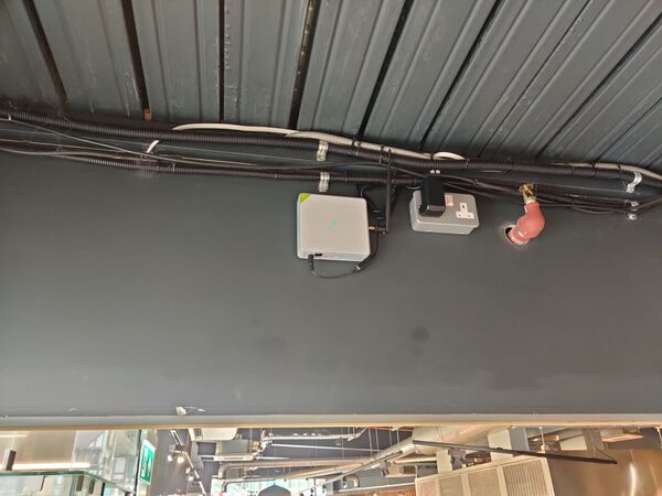
Mount the gateway on the wall above head height using appropriate anchors and screws. Ensure adequate clearance for cable connections.
The device should be mounted securely with the white face visible and accessible and cable connections on the lower edge.
Note: The device has a green status LED on top that should be visible after installation.
2. Antenna Connection

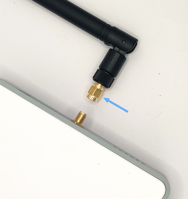
Connect the external antenna to the gold-coloured SMA connector on the side of the gateway. Ensure the gold adapter (indicated with the arrow) is present.
Hand-tighten the antenna until secure, but do not over-tighten.
The antenna should be clear of cables and obstructions. The orientation is not important.
3. Power Connection

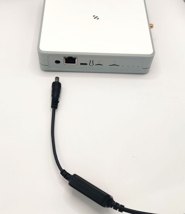
Connect the adapter cable to the gateway, and connect the power supply to the adapter cable.
Plug the power supply into a standard outlet.
Verify the gateway powers on. The LED indicator will cycle through red and blue, and turn green after 3-4 minutes.
Contact Pemberton Digital if the LED indicator does not light, or remains red even after 5 minutes have passed.
5. Final Check

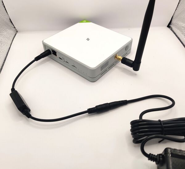
The complete installation should look similar to the images above. Ensure all cables are secured and neatly arranged.
The gateway is pre-configured and connects via 5G - no technical setup is required.
Verify the green LED indicator is illuminated.