Components Checklist
- CF-10 Advanced Occupancy sensors
- Verify the device code matches the code specified on the site floorplan
- (optional) Mounting bracket, if not using magnetic mounting
- USB-C to USB-C cable
- USB-C power supply
Step 1(a): Sensor mounting (ceiling mount sensor)
The occupancy sensor is pre-configured, and must be mounted to the ceiling as close as possible to the marked location on the floorplan.
Several options are provided for mounting. No matter the method used, the sensor must be mounted
- Within 1 metre of the location marked on the floorplan;
- On a stable surface, free of vibration (do not mount to air-conditioning ducting);
- Above head height of staff and customers;
- Within 10-20m of the occupancy gateway;
- With a clear “view” of the area to be covered;
- In a location with minimum obstructions between the gateway and the occupancy sensor, to ensure good wireless signal propagation;
- In a dry, indoor environment, clear of heat sources, condensation and water.
If in doubt, please contact Pemberton Digital for mounting advice (contact details below).
Sensor orientation
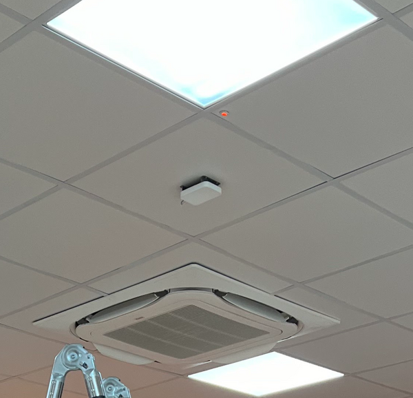
The ceiling-mount sensor must face directly downwards.
Rotate the sensor so the arrow on the sensor lines up with the arrow on the floorplan provided.
Important! Check the sensor code
Check the 5-character code on the rear of the sensor matches the code marked on the floorplan supplied.
Mounting Option 1 - Attach sensor directly to a cable tray
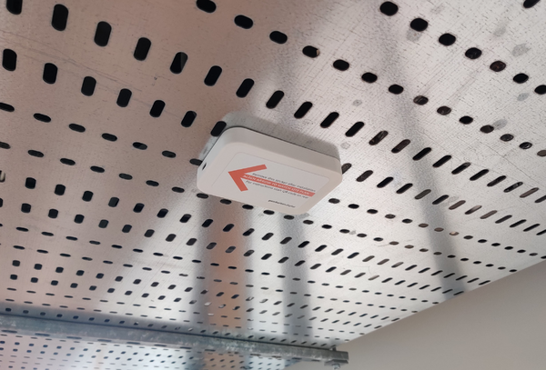
To aid mounting, the sensor includes two magnets on the rear, and it can be clipped magnetically directly to a cable tray as shown in the photo above. No bracket is required.
Ensure the sensor is oriented to match the arrow marked on the floorplan.
Remove the sensor orientation (red arrow) sticker.
Mounting Option 2 - Use ceiling mount bracket
The ceiling mount bracket allows mounting on ceiling tiles and other non-metallic ceiling surfaces.
Orient the bracket with the longer edge (marked in blue) in line with the orientation arrow marked on the floor plan.
Attach the bracket to the ceiling using appropriate screws and fixings. For ceiling tiles and plasterboard ceilings, “spring toggle” type fixings are recommended. Do not screw directly into the ceiling tile.
Use at least two fixings on either side of the bracket.
The sensor power cable may be routed through a hole in the located behind the bracket, for neat installation.
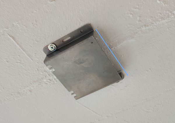
Clip the sensor magnetically to the bracket.
Ensure the sensor is oriented to match the arrow marked on the floorplan.
Remove the sensor orientation (red arrow) sticker.
Step 1(b): Sensor mounting (wall mount sensor)
The occupancy sensor is pre-configured, and must be mounted to the wall as close as possible to the marked location on the floorplan, with a specific tilt and angle.
To obtain an accurate mounting angle, a specific bracket is provided with a set tilt. The bracket is mounted using double sided tape (supplied).
The sensor must be mounted
- Within 1 metre of the location marked on the floorplan;
- On a stable surface, free of vibration (do not mount to air-conditioning ducting);
- Above head height of staff and customers;
- Within 10-20m of the occupancy gateway;
- With a clear “view” of the area to be covered;
- In a location with minimum obstructions between the gateway and the occupancy sensor, to ensure good wireless signal propagation;
- In a dry, indoor environment, clear of heat sources, condensation and water.
If in doubt, please contact Pemberton Digital for mounting advice (contact details below).
Important! Check the sensor code
Check the 5-character code on the rear of the sensor matches the code marked on the floorplan supplied.
Mounting using the supplied wall mount bracket
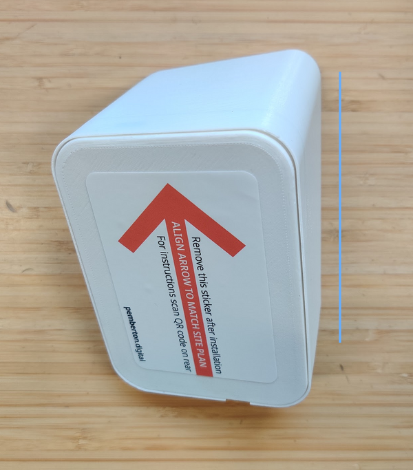
The wall-mount sensor must be mounted to a clean, dry wall using the supplied bracket, with the side of the bracket oriented vertically (the blue line below must be vertical).
- Ensure the location is exactly as marked on the floorplan supplied.
- Ensure the red arrow is facing up.
- If the wall is dirty, clean it with detergent and/or isopropyl alcohol to ensure the double sided tape adheres firmly.
Remove the backing on the double sided tape and stick the sensor and bracket to the wall. Hold it firmly in place for 20 seconds to ensure strong adhesion.
Step 2: Power Connection
The sensor must be connected to a power supply.
Route the provided USB-C to USB-C cable from the sensor back to a 13A outlet. Ensure the output has a 24-hour power supply (ie. it is not connected to a lighting circuit).
Connect the supplied USB-C power supply to the USB-C cable and plug it in to the outlet.
Ensue the USB-C cable is firmly seated on the power supply (insert the cable until you hear a click).
Power Connection Verification
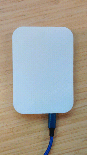
When the sensor is powered up, it will flash a white LED for 30 seconds to show that it is working correctly.
Turn on the power, and verify the sensor flashes for 30 seconds.
Step 3: Check measurements and power
- If it was necessary to install the sensor in a location different to marked, measure the distances to the nearest wall or feature and mark this on the floor plan.
- Take a photograph of the sensor showing the sensor and surroundings.
- Double check power is connected and turned on.
- Send the annotated plan and photographs to info@pemberton.digital.